Sensors
For ZigBee sensors and switches check Raspbee module
Switches
The Dimmer Switch and Tap Switch are almost identical, the only difference is that dimmer switch can control the lights without the bridge (for this reason bridgeIp is declared as an array to setup more IP’s), and the button codes are different.
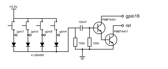
Circuit diagram
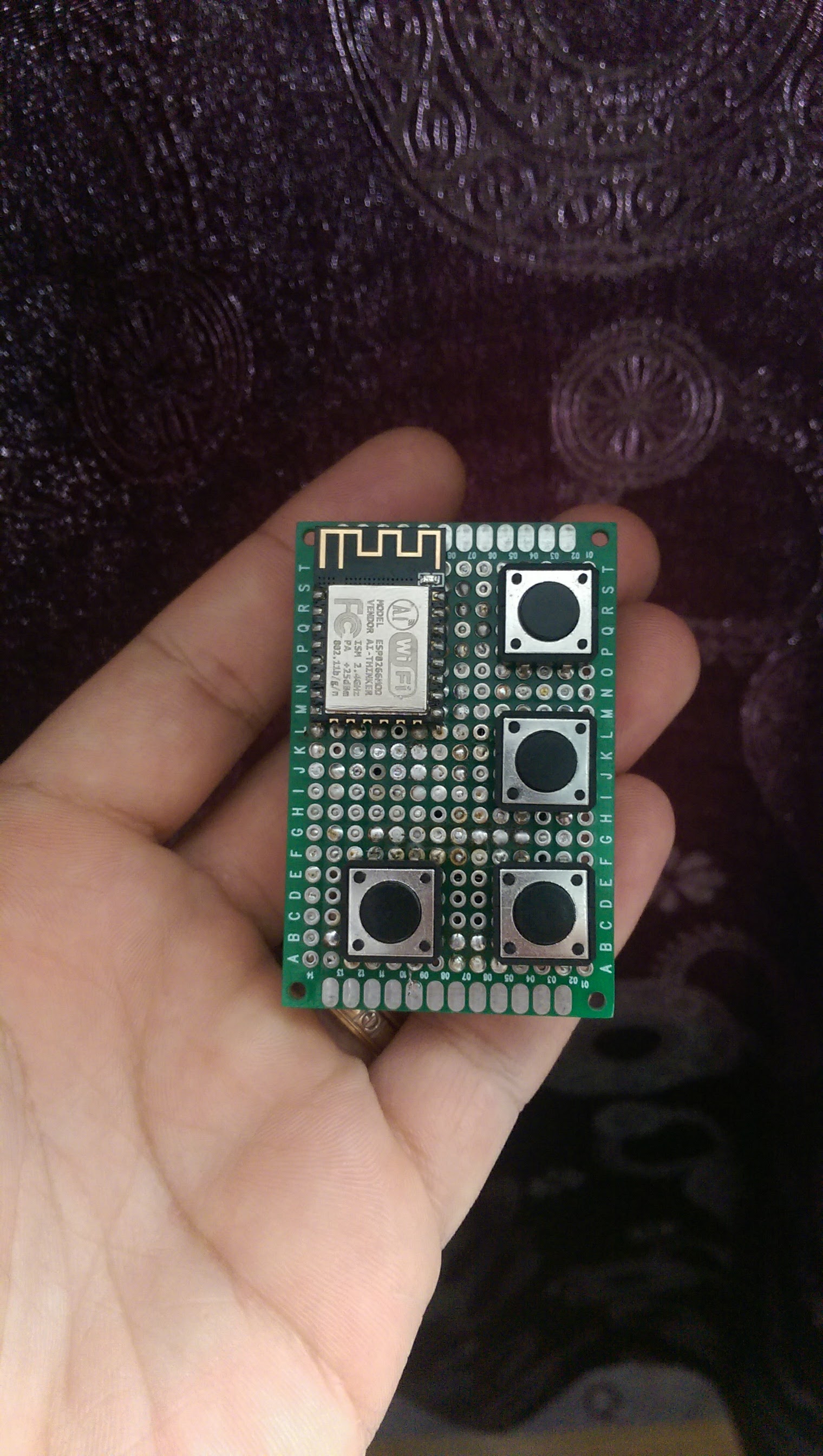
Device Prototype
How it works
When the switch powers on, a GET request will be sent to the bridge , ex: http://{bridgeIP}/switch?mac=xx:xx:xx:xx:xx:xx&devicetype=ZLLSwitch
The bridge will then check based on MAC address if the switch is already registered or not.
If not, it will register making it available for configuration in the Hue application.
After 3-5 seconds the ESP8266 will enter deep sleep mode and will consume less than 20uA.
On every button press there will be a short negative pulse on ESP8266 RST pin that will wake up the device.
It will then read the input pins to check what button was pressed and send a request like this: http://{bridgeIP}/switch?mac=xx:xx:xx:xx:xx:xx&button=1000
The bridge will then process all rules and perform the action configured for this button.
Motion Sensor
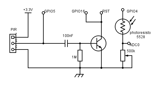
Circuit diagram
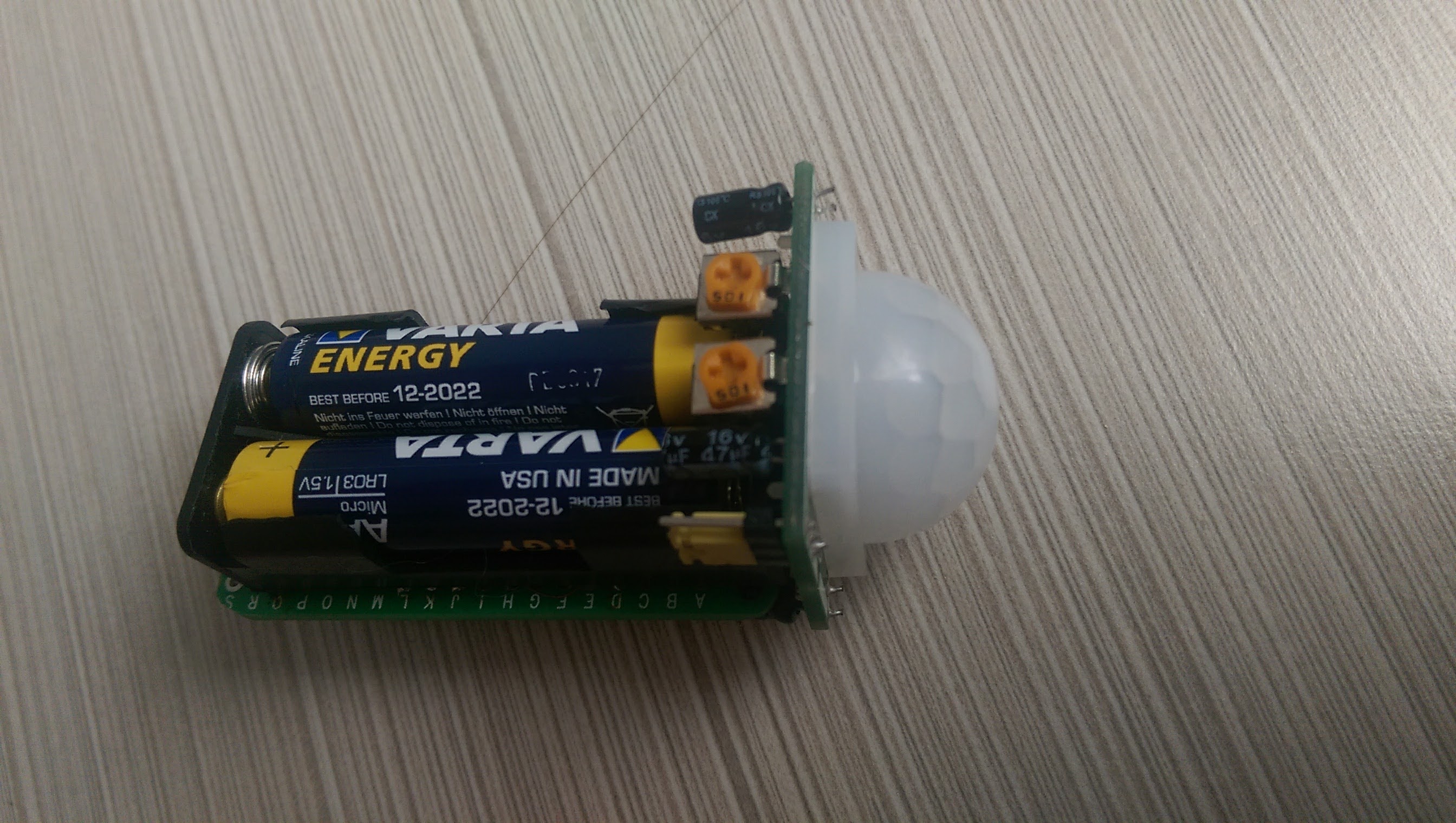
Device prototype
How is working
Exactly like the switches, the sensor will be registered on power on with a GET request: http://{bridgeIP}/switch?mac=xx:xx:xx:xx:xx:xx&devicetype=ZLLPresence and configuration can then be done from the Hue application.
The ESP8266 will wake up from deep sleep on every PIR positive signal on the GPIO5 pin and every 20 minutes to send the light sensor data.
Request example: http://{bridgeIP}/switch?mac=xx:xx:xx:xx:xx:xx&lightlevel=46900&dark=false&daylight=true&presence=true&temperature=2300
It is important to choose a low power PIR that can run on batteries for many months.
The PIR used in my example is an HC-SR501, that is very common in DIY projects.
To increase the battery life I removed the 3.3V voltage regulator as this is not needed with batteries.
GPIO4 will output +3V only when the light level is measured in order to lower the power consumption.